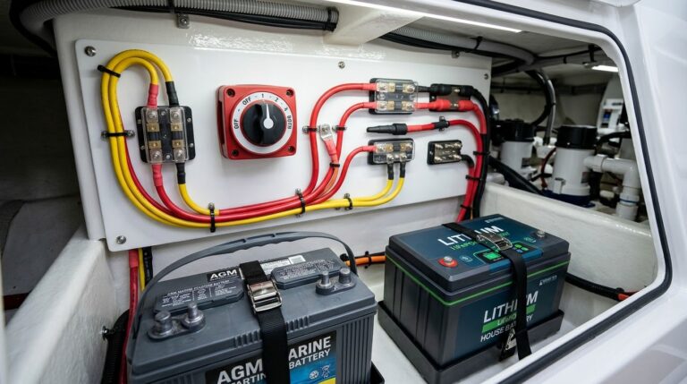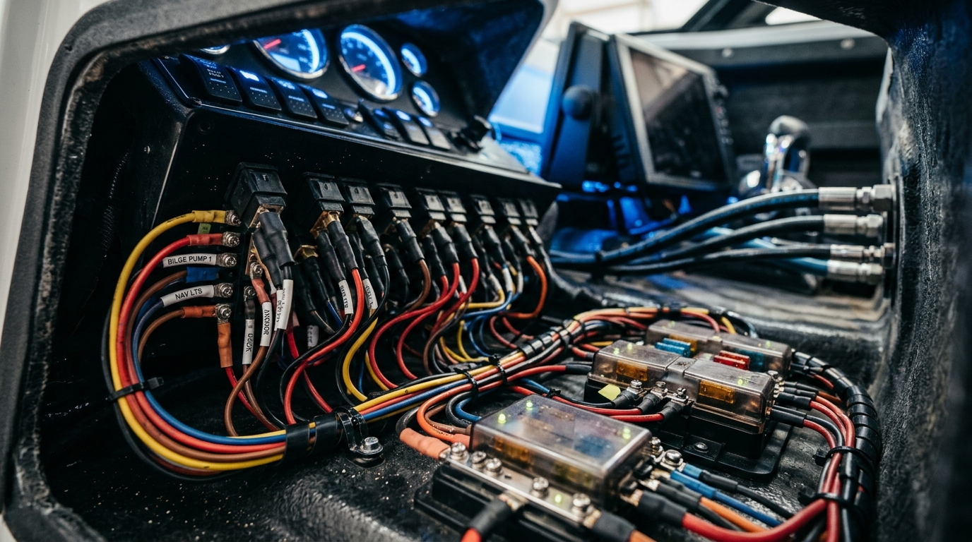
Installing a reliable marine dual battery switch wiring configuration is one of the smartest electrical upgrades any powerboat or fishing boat owner can perform. Nothing ruins a peaceful day on the water faster than discovering that hours of running livewell pumps, stereo amplifiers, and large chartplotters at anchor have completely drained your battery, leaving you stranded with an engine that refuses to start.
Implementing proper marine dual battery switch wiring divides your electrical ecosystem into two dedicated banks: a high-cranking starting battery reserved exclusively for firing up your outboard or inboard engine, and a deep-cycle house battery designed to supply continuous accessory loads. In this definitive guide, certified marine technicians explain 1-2-BOTH-OFF switch positions, wiring diagrams, automatic charging relays, and ABYC wire gauge sizing.
How a 1-2-BOTH-OFF Marine Dual Battery Switch Operates
The standard manual 4-position rotary marine battery switch features four distinct operating selections. Understanding the mechanics of your marine dual battery switch wiring is critical to avoiding dead batteries:
| Switch Position | Electrical Circuit Status | Recommended Operational Use Case |
|---|---|---|
| Position 1 | Battery Bank 1 connected to engine and house loads | Normal cruising on odd-numbered days, using Bank 1 as primary starting battery |
| Position 2 | Battery Bank 2 connected to engine and house loads | Normal cruising on even-numbered days, alternating wear between battery banks |
| BOTH / ALL | Battery Bank 1 and Bank 2 connected in parallel (12V doubled Ah) | Emergency jump-starting only! Never leave in BOTH when drifting or anchored. |
| OFF | All battery positive terminals completely disconnected | Moored at dock, trailered storage, prevents all parasitic current drains |
Warning: In traditional manual marine dual battery switch wiring, leaving the switch in the “BOTH” position while anchored allows house accessories to drain both batteries simultaneously. If one battery has a bad cell, it will draw down the healthy battery beside it, leaving you with zero cranking power.
Standard Marine Dual Battery Switch Wiring Schematics
To wire a standard 4-position manual selector switch (such as a Blue Sea Systems 6007 or Perko switch), follow this ABYC-compliant terminal layout:
- Terminal 1 (Bank 1 Positive): Run a red heavy-duty marine battery cable from the positive (+) terminal of Battery 1 to Post 1 on the back of the selector switch.
- Terminal 2 (Bank 2 Positive): Run an identical red marine cable from the positive (+) terminal of Battery 2 to Post 2 on the selector switch.
- Common / Output Terminal: The large central lug on the switch feeds power to your vessel. Connect the positive starter cable from your engine and the positive feed to your main distribution fuse panel here.
- Shared Negative Ground Busbar: Connect the negative (-) terminal of Battery 1 and Battery 2 together using a black or yellow marine cable of equal gauge to a common negative ground busbar. The engine ground cable and DC negative distribution return must also attach to this shared busbar.
Upgrading to an Automatic Charging Relay (ACR)
While basic manual switches work, modern boat owners vastly prefer an automated system combining a Dual Circuit Plus switch with an Automatic Charging Relay (ACR) (such as the Blue Sea Systems 7650 “Add-A-Battery” kit). Integrating an ACR into your marine dual battery switch wiring delivers three massive operational advantages:
- Set-and-Forget Convenience: The main switch simply has “ON”, “OFF”, and “COMBINE”. You turn it to “ON” when boarding and “OFF” when leaving the boat.
- Automatic Battery Isolation: When the engine starts, the ACR isolates the house electronics from the cranking circuit, protecting sensitive GPS chartplotters and sounders from voltage spikes.
- Automated Dual-Bank Charging: While running, the outboard alternator charges the starting battery first. Once the starter battery reaches 13.0V for 90 seconds, the ACR automatically closes its contacts, sharing alternator current to charge the house battery. When you stop the engine, the ACR senses voltage drop and decouples the banks automatically.
ABYC Cable Gauge & Circuit Protection Sizing
Marine electrical standards published by the American Boat and Yacht Council (ABYC) require that all battery cables withstand maximum starter inrush current without exceeding a 3% voltage drop:
| Engine Horsepower | Total Cable Run Length (Round Trip) | Recommended AWG Wire Size | Terminal Stud Fuse Rating (MRBF) |
|---|---|---|---|
| Under 90 HP | Up to 10 feet | 4 AWG Tinned Copper | 150 Amp MRBF Fuse |
| 115 – 200 HP | 10 to 15 feet | 2 AWG or 1/0 AWG | 200 – 250 Amp MRBF Fuse |
| 225 – 350+ HP V6/V8 | 15 to 25 feet | 2/0 AWG or 4/0 AWG | 300 Amp MRBF Fuse |
Crucial Safety Rule: Always install marine-rated battery terminal fuses (MRBF) directly on the positive battery posts or within 7 inches of the battery. If a battery cable chafes against an engine bracket, an unfused cable will glow white-hot and ignite a fiberglass fire in seconds.
Explore our foundational marine battery care guide to compare deep-cycle AGM vs. Lithium chemistries, and consult our marine electrical systems 101 guide for DC color-coding standards.
Frequently Asked Questions About Marine Dual Battery Switch Wiring
Can I turn my marine dual battery switch while the engine is running?
Modern “make-before-break” switches allow you to rotate between Position 1, Position 2, and BOTH while the engine is running without interrupting electrical flow. However, never turn the switch to OFF while the engine is running; doing so instantly disconnects the load on the alternator, causing an instantaneous high-voltage spike that burns out the alternator rectifier diodes.
Can I combine an AGM starting battery with a Lithium (LiFePO4) house battery?
Yes, but you should not connect them directly in parallel with a basic manual switch in the “BOTH” position, as lithium and AGM batteries have different resting voltages (12.8V vs 13.3V). Instead, use an Automatic Charging Relay (ACR) or a DC-to-DC marine charger to isolate the chemistries while charging both efficiently.
Should the automatic bilge pump be wired through the dual battery switch?
No. ABYC electrical standards explicitly mandate that automatic bilge pump float switches must be wired directly to the positive terminal of a battery bank through an inline waterproof fuse, bypassing the master switch completely. This ensures that even when you switch the boat to “OFF” and leave for weeks, the pump will automatically evacuate rainwater from the bilge.
What happens if I forget the battery switch in the “BOTH” position?
If you leave the switch in “BOTH” while drifting with the engine off, running accessories will draw current from both battery banks equally. If you drain the batteries listening to music or running aerators, neither battery will have enough reserve cranking amps to start your engine.
Published by Boat Maintenance Guide Electrical Systems Desk. Inspected in accordance with American Boat and Yacht Council (ABYC) E-11 AC and DC Electrical Systems on Boats standards.